Cadstar Library Component for Eurotech Catalyst CPU Module

I’ve been looking at doing some designs using the Eurotech Catalyst CPU module board featuring the Intel Atom processor.  This component poses some design challenges for Zuken CADSTAR library manager, mainly because there are two connectors used by the module.  There is a 220 pin high density interconnect connector, and a 14 pin 2mm square post header for the power supply.

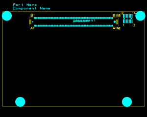
Image of pcb footprint of Eurotech Catalyst module

Catalyst Footprint

The origin for the PCB footprint is the center of the high density connector.  Generating a bill of materials automatically with all of the hardware and connector bits at design completion can be an issue.  What I’ve done in the past is simply assign an attribute whose value is a file path to a text file that includes all the separate bits and pieces needed for using this component. In this way I can automatically create a second level BOM for this component when running the raw BOM report through a post-processing step.  However, one thing I haven’t sorted out yet for this part yet is how to generate the origin of the 14pin header for the manufacturing data output.  Possibly I need another attribute which defines the relative offset(s) from the component origin of any additional parts that go with this particular footprint.  I’m open to suggestions.  Supposedly there’s coming soon to a version of CADSTAR the ability to assign multiple part numbers to a single component in order to make a structured second level bill of materials right from the library.

A CADSTAR 10 format library component archive file for the Catalyst module is here.   Please check the pin assignments carefully against the datasheet for the module!  This hasn’t been proven on any designs just yet.   There are some tricky PCB design issues when using this module, primarily due to the very high speed signals on some of the interconnects. This module has two PCIe x 1 expansion ports running at 2.5GHz, 8 USB high speed ports, 2 MMC4 ports (8 data bits @ 48MHz) as well as 1 standard SDIO port, along with LVDS and DVO video ports and Intel HD audio, among other things. Controlled impedance, differential pair routing and skew control will be necessary when deploying this component.  If you have Zuken PREditor HS then you’ll be all set!

-Jeff

RoHS Manual Soldering Hints

For several years F.O.M. Systems has been working with various lead free (RoHS compliant) soldering alloys for printed circuit board assembly. Our experiences with these materials has ranged from the “hardly any difference” to “virtually unusable”. Depending on the alloy used you may have a similar range of experiences. Besides the supposed environmental advantages of lead free solders the main practical advantage associated with these materials is that they create solder joints of much higher strength than older tin/lead solders. But that’s pretty much where the advantages leave off.

Once the pcb reflow process has been tweaked and a suitable solder paste has been selected process yields are equivalent to older tin/lead processes. Since the reflow temps can be about 20oC higher than tin/lead processes it’s even more important that components are kept appropriately moisture-free prior to assembly. Also of note but probably not wholly related to RoHS processes is that we get better process yield with BGA footprints of any size over TQFP and TSSOP components. But you’d better get it right the first time since rework can be considerably more difficult with RoHS soldering processes.

Working with RoHS solder

If you are used to working with a very small tip on your soldering iron (such as a Weller NT1 tip) you should switch to working with a larger tip such as an equivalent to the Weller NT4 or NTAX. Smaller tips simply don’t have the thermal mass needed to work properly with RoHS solders. Don’t turn up the iron temperature too far (I use 660 to 680F/349 to 360C) since this will cause the flux to burn and make adequate heat transfer even more problematic. Speaking of flux, a more aggressive flux will be needed, and lots of it, when doing hand soldering of RoHS materials. Something like Kester #2331-ZX works well. Having an iron tip cleaner handy will be helpful as well as keeping lead free tips clean is a lot more of a chore than with leaded solders.

Note that it is unwise to mix leaded and lead-free solders, not just from a legal or environmental standpoint. As little as 0.5% of lead contamination of a lead free joint will greatly weaken the joint and lead to premature failure. Metalurgically it’s OK to use leaded solder to affix lead free components since enough lead will be present in the alloy to prevent attachment problems, but do NOT use RoHS solder to affix components with tin/lead plating on their leads as this will result in weakened solder joints.

RoHS solder joints look different. The material doesn’t wet the joints as readily as tin/lead solder, and when cooled has a dull “frosty” appearance. This is what makes using plenty of flux so important as it’s much more difficult to distinguish a “cold” solder joint when using RoHS solders. Also the transition zone of RoHS alloys is much narrower than tin/lead. One moment it’s solid, the next it runs like water. There’s no in-between semi-molten state like there is with tin/lead solders. If you’ve done any soldering on copper pipe used for potable water supply in the last 15 years using tin/antimony solder you know what I mean.

The easiest alloy to use for hand soldering seems to be SAC3. This is an alloy of 0.6% copper, 2.5 to 3% sliver, the rest tin. Of course it’s the most expensive due to the high silver content. Kester 331/66 is a good choice, as is Warton Metals S.A.C.3 with a 2% core of Future HF Fast Flow flux. Remember to use plenty of flux both on the board and component leads, and keep those tips clean!

BGA Solder Joint Failure (pad cratering) on RoHS PC

I’ve been working on a new project using the Intel Atom processor and 945GSE chipset.  In the platform design guide that Intel published they have various recommendations for routing traces to the corners of BGA PCB footprints for the parts and I was curious as to why these were being recommended.   It turns out I’ve been fortunate in my past experience with RoHS-based designs since most of the boards I work on are small, fairly rigid (most are 1.6mm thick) and the BGA components were few and of fine pitch. However, there is an ugly failure mode with RoHS process boards and BGA’s which has come to be known as “pad cratering”. This is a bit of a misnomer, since the “crater” is the space left vacant when a BGA ball pad lifts off the board.

Causes of pad cratering

Simply put, pad cratering is merely the failure of the resin bond between the board and the surface ball pads of a BGA footprint.  This has been exacerbated by RoHS because of the higher reflow temperatures needed (embrittles the resin) and the greater hardness of RoHS compliant solders.  There are at least two main causes: mechanical stress due to thermal cycling of the board during reflow, and stress on the joints caused by board flexing during handling and other mechanical shocks.  The failures normally begin at the outside corners of the BGA package and may not be apparent at first if the connecting traces to the pads don’t immediately fracture.  The most common electrical failure point is at the perimeter of the ball pad where a routing trace connects to the pad.

Dealing with pad cratering

Note that this heading does not say “preventing pad cratering” as it appears that simply attempting to prevent pad cratering will not yield significant increases in board reliability. The most extreme example I’ve seen in the attempt to prevent pad cratering  is to apply epoxy to the 4 corners of each BGA package to provide mechanical stress relief for the corner pads.  For most of us however that’s simply not practical.  What has apparently been working for me is to break out the corner BGA pads and those of the next row back on the diagonal with trace widths equal to the diameter of the ball pads.
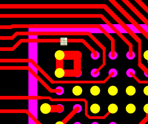
Northwest corner of PXA270 footprint showing pad bonding

PXA270 Corner Ball Pads

In this view the yellow shapes represent pads with a 4mil via-in-pad blind via connecting to the second layer, purple pads do not have vias. Via-in-pad was mentioned in one study I read as another possible way to mitigate pad cratering but that not enough research had been done to determine its effectiveness. The idea behind the wide traces at the pad is to eliminate copper trace fracturing at the pad perimeter.  Evidently the dual approach of using fat traces plus via-in-pad has worked for me as none of the boards on which I’ve used this approach have yet to experience a failure due to pad cratering. These boards are only 0.8mm thick and are used in a hand-held product, unfortunately a prime candidate for pad cratering failure. But so far so good…

It’s been suggested that for attaching traces to the corner ball pads one should route away from the pad at a 45 degree angle relative to the pad with a wide trace for about 1.2mm, then neck down to normal routing width and go off in the direction of the route. The image below illustrates this:
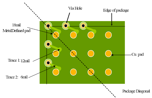
Using short stubs to mitigate cratering

Using short fat trace stub to mitigate pad cratering

Another approach to reducing the stress at the pad to trace boundary is to use solder mask defined pads rather than metal defined pads for the entire array. Jon Manning (you can find him on Linkedin) suggested using solder mask defined pads for the first 3 rows in on the diagonal, using the same solder mask size as pad metal size for the balance of the array, and increasing the pad metal size in the corners appropriately. Depending on the ball pitch of your parts and your board layer structure it seems that some combination of these approaches should work for you to sufficiently mitigate the effects of pad cratering. Since shock and flexing are a significant contributor to pad cratering that’s one place the mechanical design group can make contributions.  We don’t use solder mask defined pads on all ball pads as a rule since metal defined pads appear to have somewhat highter soldering reliability and less problems with joint cracking.

Nicholas Vickers, Kyle Rauen, Andrew Ferris and Jianbiao Pan of Cal Poly State University published a study of BGA soldering reliability. Their research conclusions can be found here.  Also, thanks to Jon Manning for sharing his considerable pcb design experience.

-Jeff